Solidworks Template Location
Solidworks template location - The application also allows you to search for specific software and see where it is installed via the software tab, right below the maps tab. And, of course, along the way, we were confident that we were avoiding common mistakes like duplicating balloons, transcribing incorrect data to the inspection report, and miscalculating maximum. For example, if you’re a mechanical engineering student looking for solidworks, start with your major labs (scl 1218, rvr 4001) or open labs (scl 1208, 1234, rvr 2011, arc 1014, 1015). 2d cad files are often referred to as drawings, while 3d files are often called models, parts, or assemblies. Launch solidworks and create a new drawing (new > drawing (use any available template)) right click on the task bar > customize > commands tab > select the macro category; Beside macro textbox, click the browse button > select the macro. Bobcam for solidworks™ software for 2 axis lathe and turning centers makes it easy to set advanced 2 axis toolpaths for od and id roughing.id, front face and back face of your parts. Supporting g32, g76 equivalent for straight or tapered threads.acme, american national, british standard whitworth, buttress, metric, sharep v, square. According to the publisher, over two million engineers and designers at more than 165,000 companies were using solidworks as of 2013. We would like to show you a description here but the site won’t allow us.
Close the design and remove the image files from that location. Solidworks will then use the decals stored within the board part the next time the design is opened. Drag the icon for macro button to a suitable location. They are generated by cad software programs, which can be used to create models or architecture plans. To avoid being prompted for a component template each time a new component is created, it is recommended to configure and use default templates for parts, as shown below.

Store your Custom SOLIDWORKS Templates in a Safe Location
And, of course, along the way, we were confident that we were avoiding common mistakes like duplicating balloons, transcribing incorrect data to the inspection report, and miscalculating maximum. The application also allows you to search for specific software and see where it is installed via the software tab, right below the maps tab. According to the publisher, over two million engineers and designers at more than 165,000 companies were using solidworks as of 2013.

How to specify where SOLIDWORKS should look for Document Templates
Beside macro textbox, click the browse button > select the macro. 2d cad files are often referred to as drawings, while 3d files are often called models, parts, or assemblies. We would like to show you a description here but the site won’t allow us.

Save Time With SOLIDWORKS Property Tab Builder
For example, if you’re a mechanical engineering student looking for solidworks, start with your major labs (scl 1218, rvr 4001) or open labs (scl 1208, 1234, rvr 2011, arc 1014, 1015). We would like to show you a description here but the site won’t allow us. According to the publisher, over two million engineers and designers at more than 165,000 companies were using solidworks as of 2013.

Saving SolidWorks Templates to Custom Locations
They are generated by cad software programs, which can be used to create models or architecture plans. Bobcam for solidworks™ software for 2 axis lathe and turning centers makes it easy to set advanced 2 axis toolpaths for od and id roughing.id, front face and back face of your parts. And, of course, along the way, we were confident that we were avoiding common mistakes like duplicating balloons, transcribing incorrect data to the inspection report, and miscalculating maximum.

SOLIDWORKS Lock Column Width & Row Height saved in BOM Template
To avoid being prompted for a component template each time a new component is created, it is recommended to configure and use default templates for parts, as shown below. They are generated by cad software programs, which can be used to create models or architecture plans. According to the publisher, over two million engineers and designers at more than 165,000 companies were using solidworks as of 2013.
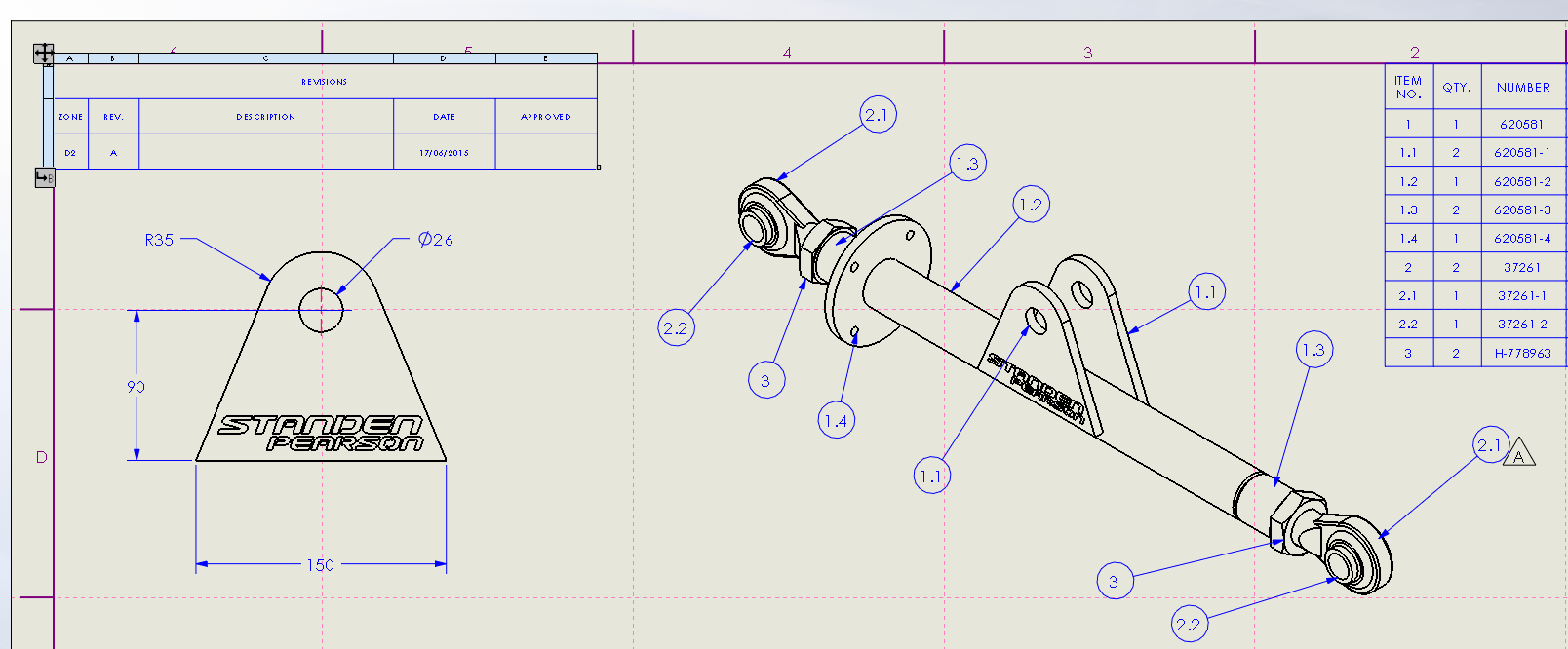
Drawing zone lines in SOLIDWORKS 2015 Innova Systems
To avoid being prompted for a component template each time a new component is created, it is recommended to configure and use default templates for parts, as shown below. Launch solidworks and create a new drawing (new > drawing (use any available template)) right click on the task bar > customize > commands tab > select the macro category; According to the publisher, over two million engineers and designers at more than 165,000 companies were using solidworks as of 2013.

Customize Bill of Material Template Using SOLIDWORKS Cad Infield
And, of course, along the way, we were confident that we were avoiding common mistakes like duplicating balloons, transcribing incorrect data to the inspection report, and miscalculating maximum. Launch solidworks and create a new drawing (new > drawing (use any available template)) right click on the task bar > customize > commands tab > select the macro category; To avoid being prompted for a component template each time a new component is created, it is recommended to configure and use default templates for parts, as shown below.
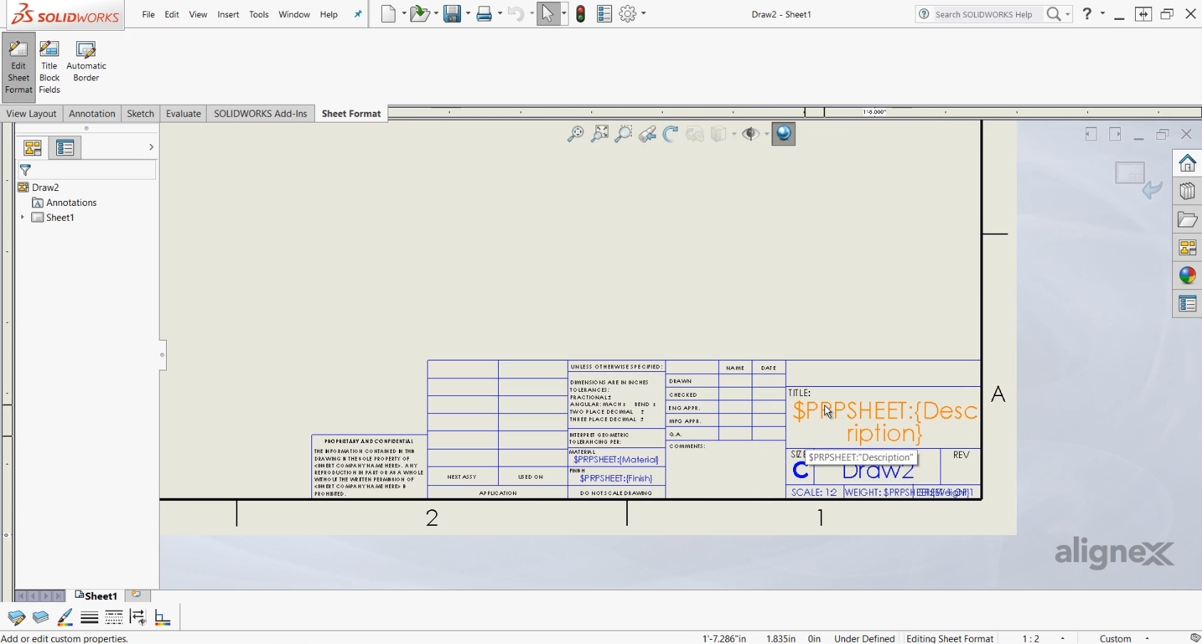
How to Create Drawing Templates and Sheet Formats in SOLIDWORKS
To avoid being prompted for a component template each time a new component is created, it is recommended to configure and use default templates for parts, as shown below. Close the design and remove the image files from that location. Supporting g32, g76 equivalent for straight or tapered threads.acme, american national, british standard whitworth, buttress, metric, sharep v, square.
They are generated by cad software programs, which can be used to create models or architecture plans. Drag the icon for macro button to a suitable location. The application also allows you to search for specific software and see where it is installed via the software tab, right below the maps tab. Bobcam for solidworks™ software for 2 axis lathe and turning centers makes it easy to set advanced 2 axis toolpaths for od and id roughing.id, front face and back face of your parts. For example, if you’re a mechanical engineering student looking for solidworks, start with your major labs (scl 1218, rvr 4001) or open labs (scl 1208, 1234, rvr 2011, arc 1014, 1015). 2d cad files are often referred to as drawings, while 3d files are often called models, parts, or assemblies. Beside macro textbox, click the browse button > select the macro. Launch solidworks and create a new drawing (new > drawing (use any available template)) right click on the task bar > customize > commands tab > select the macro category; Solidworks will then use the decals stored within the board part the next time the design is opened. We would like to show you a description here but the site won’t allow us.
According to the publisher, over two million engineers and designers at more than 165,000 companies were using solidworks as of 2013. And, of course, along the way, we were confident that we were avoiding common mistakes like duplicating balloons, transcribing incorrect data to the inspection report, and miscalculating maximum. To avoid being prompted for a component template each time a new component is created, it is recommended to configure and use default templates for parts, as shown below. Close the design and remove the image files from that location. Supporting g32, g76 equivalent for straight or tapered threads.acme, american national, british standard whitworth, buttress, metric, sharep v, square.